HarnesSYS incorporates applications for each stage in the design lifecycle of electrical wiring systems. The common platform facilitates efficient reuse of existing designs and flawless transfer of information from one stage to the next. Adjustments and corrections made to the original design in one application are automatically picked up by the other design applications. Built-in design checks ensure data integrity throughout the design lifecycle and specifically before release for production.
Functional Design
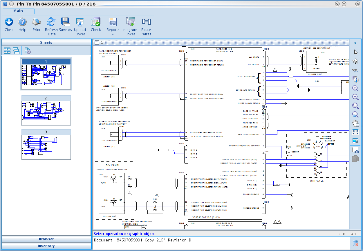
Schematic pin-to-pin diagrams specify the power and signal distribution between devices using HarnesSYS’s intuitive graphic editor. If the functional design was created using other software, the raw data can be imported into HarnesSYS and used as a source to generate a schematic Pin-To-Pin diagram quickly and automatically. This not only guarantees that the schematic will be true-to-design but also saves a considerable amount of time. The imported data is saved as a HarnesSYS document that can be referred to later for comparison and verification of the final design.
Click Image To Enlarge
Logical Design
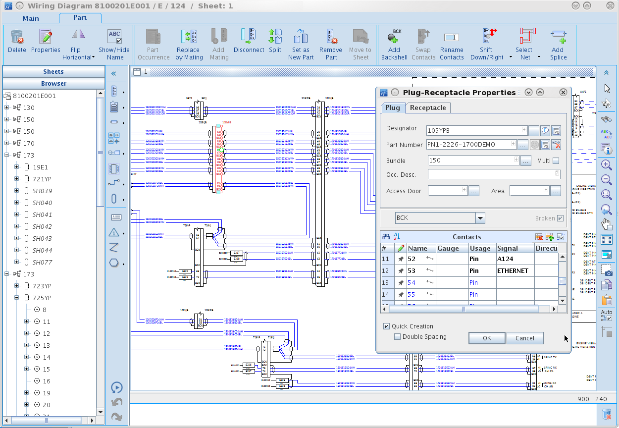
The HarnesSYS system wiring diagram uses the same graphic editor as the pin-to-pin diagram, making the transition from one to the other smooth and simple. The user experience emphasizes efficiency, reuse, ease of use and prevention of errors. HarnesSYS captures the design data directly from the schematic diagram and integrates it into the central database for further processing into part lists, wire lists, manufacturing reports and technical publication.
Wiring diagrams are drawn using HarnesSYS’s proprietary graphic editor. Special features make design fast and intuitive.
Smart Graphics
Objects in the diagram are linked to the part library and database, so the designer can access part and wire properties for each object in the diagram by simply clicking on it. Part properties in the diagram include a graphic display indicating which contacts already have wires connected to them, whether in the current wiring diagram or any other system wiring diagram.
Special Copy/Paste Features
Many projects start with pre-existing designs from previous vehicles. In other cases, systems from one design variant are copied to another variant and then modified. Special features in HarnesSYS support reuse, modification and adaptation using this unique feature.
Context Driven Toolbars
Only the buttons relevant to the selected objects are visible, eliminating screen clutter. Large icons and quick shortcuts minimize lag time.
Automatic Routing
Click on two parts, or specific contacts, and the wires between them are routed automatically.
Repetitive Actions
Repetitive actions are handled intuitively with minimum effort, saving time so you can focus on being more productive.
When it comes to complex projects, there are many considerations related to budget, schedule and quality. Design errors can be costly and cause schedule overruns. The wiring diagram is the source for a large amount of design data, and therefore there is a strong emphasis on error prevention in HarnesSYS.
Design checks before the data is captured from the wiring diagram to the database:
Catch inadvertent errors in the wiring design
Check compliance with design rules and company policies.
Examine data form the current system design along with other systems sharing the same harness to check for conflicts or duplicate connections.
Powerful query tools enable you to scan the design and filter results as necessary, to analyze and detect design flaws.
Click Image To Enlarge
Click Image To Enlarge
Physical Design
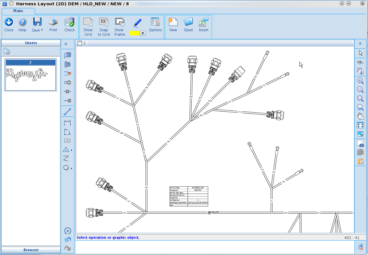
The HarnesSYS suite generates harness layout diagrams which are schematic representations of harness assemblies as if they were straightened and flattened onto a single plane. These drawings add lengths to each segment based on the physical constraints of the aircraft or vehicle, and information regarding labels, markers and protective sleeves. The harness layout diagram may be created using HarnesSYS or easily imported from MCAD models avoiding data transfer errors and ensuring the highest design quality.
HarnesSYS can also produce formboard/assembly board diagrams to represent the physical bundle’s topology in actual size.
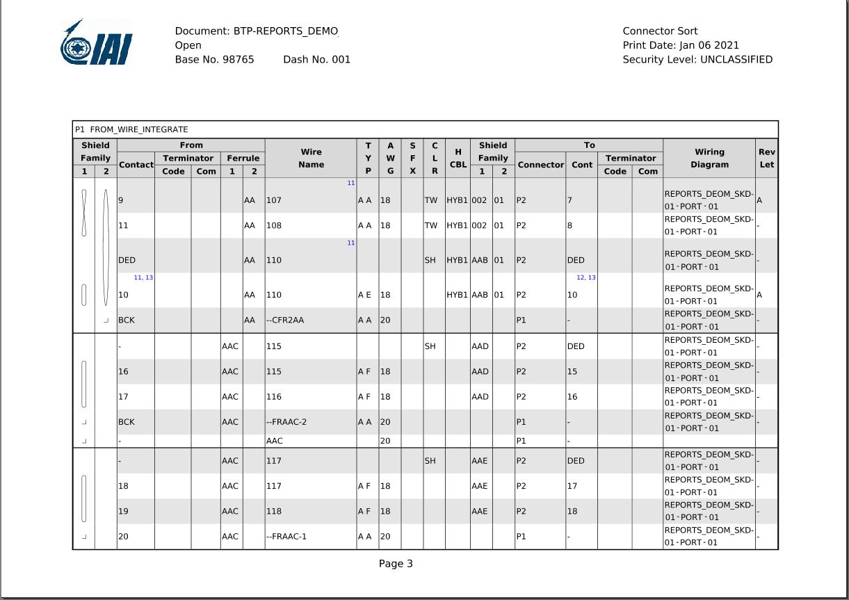
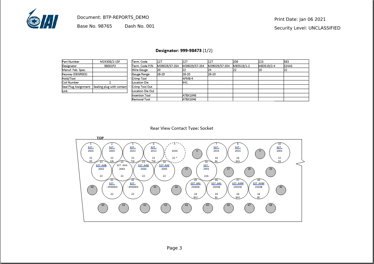
Build-to-Package
The end design output for manufacturing is a Build-to-Package (BTP) set of automatically generated documents that include a detailed part list, wire list, layout diagram and specialized reports for the various stages of harness manufacture using standard and customizable templates containing all the relevant data.
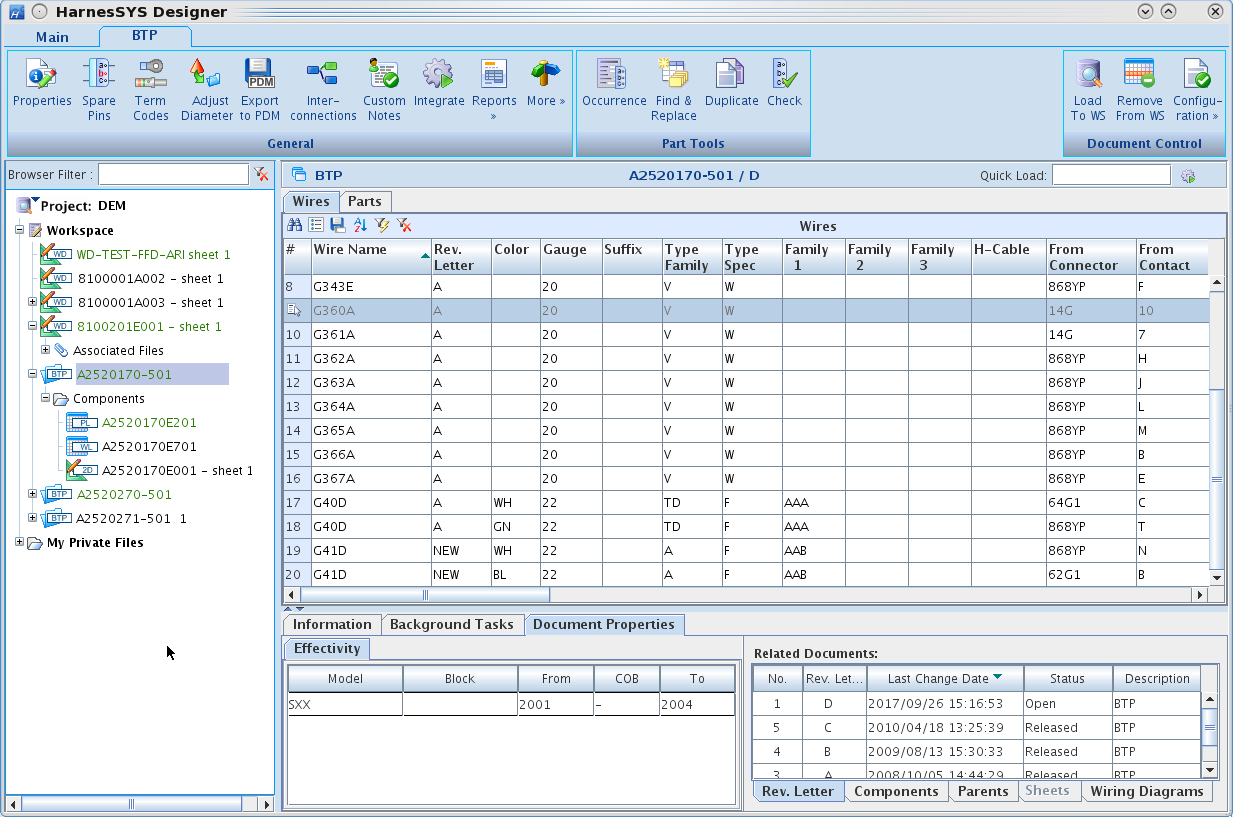
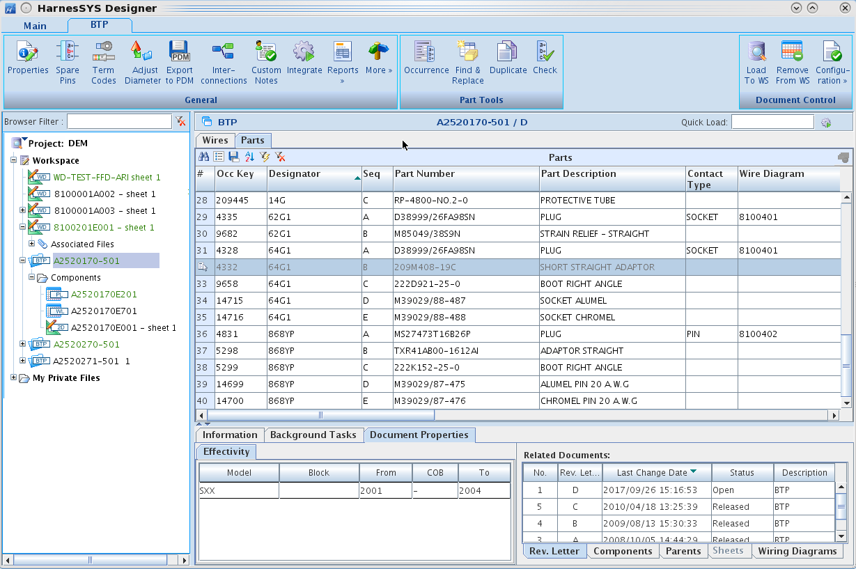
Each BTP can be traced back to its respective system diagrams, and each wiring design can be traced back to its pin to pin diagram. This provides traceability to manage change.
The HarnesSYS Designer allows the user to navigate between BTP documents and view all of the relevant information for each BTP. Part and wire lists can be viewed on customized screens with all of their specifications. Documents related to the BTP such as previous versions, wiring diagrams and layout diagrams are listed in a window at the bottom right.
Click Images To Enlarge
Technical Publications
Service documentation can be generated directly from engineering data and schematic diagrams. Large electrical schematic diagrams can be split into multiple sheets, sized so that they are easily viewable in hardcopies or electronic manuals, while maintaining electrical design integrity.